

Merlin’s Nest ~ Heybrook Bay, Devon.
Client : Private.

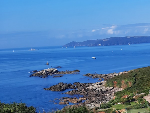
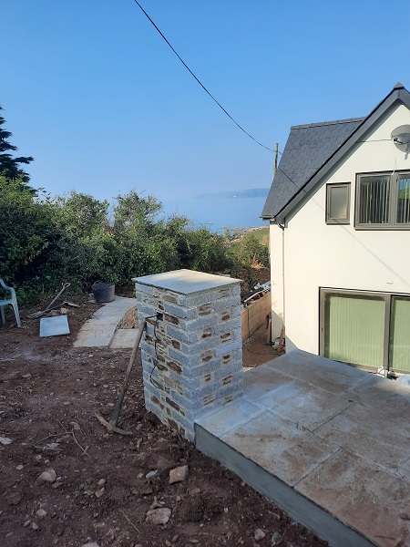
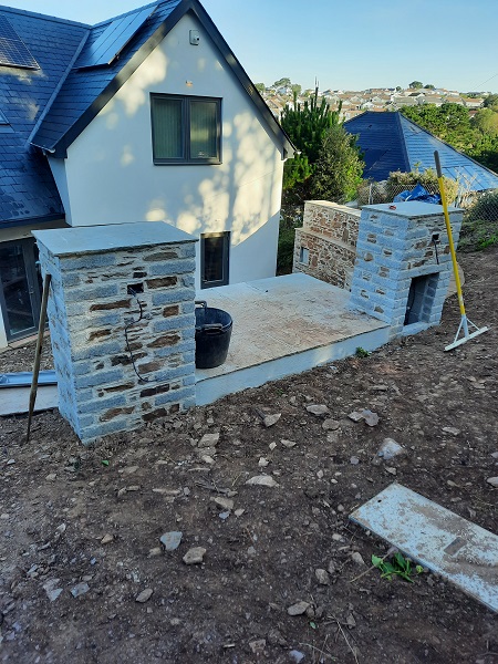
Merlin’s Nest is elevated high up along the South Devon coast on a hillside overlooking Heybrook Bay commanding far reaching views across the sea to the Rame Head Peninsula in Cornwall and beyond.
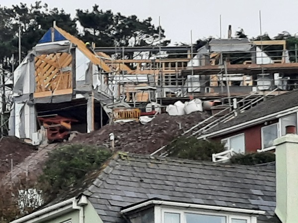
Very often we get called in to carry out the work on some amazing projects, but Merlin’s Nest really was an exception and certainly a challenge to say the least. On a scale of one to ten this project was definitely right up there amongst some of the best projects we have ever had the privilege to be involved in. This case study is quite detailed and has loads of images for you to look through, but this is exactly how we went about creating it. We hope you like reading about this just as much as we did creating it. We were initially contacted by the clients enquiring if we were willing to build them a retaining wall at the rear of their house, a quality high end new build which they were in the midst of building. We were told that they already had the stone on site but had absolutely no idea of what they wanted except that they would like a barbeque, a water feature and they would also require some steps building and it had to be something special. Easy enough we thought, so we arranged a pre-site visit to talk things through. So one overcast day we turned up at Heybrook Bay and spotted the building site high up on the hillside.
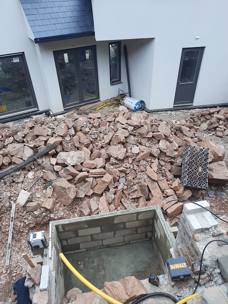
After climbing about a hundred feet or so, up a forty-five degree incline, we eventually made it up to the house. On meeting the clients, and getting our breath back, we were taken around to the back of the new property to see exactly where the new retaining wall was going to be built, only to be confronted with a scene that one could only describe as being a bomb site.
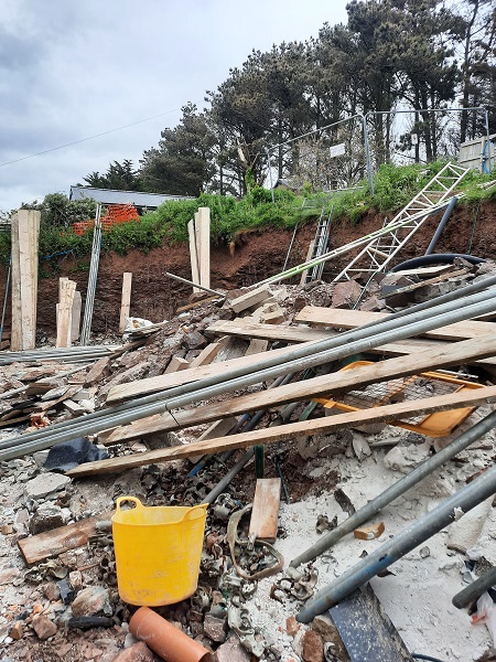
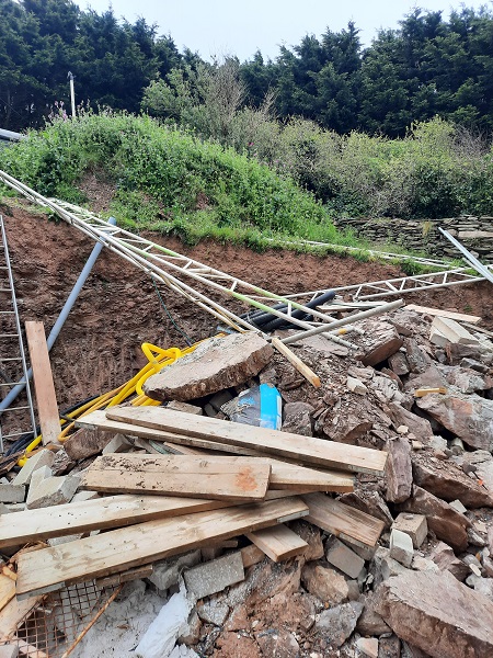
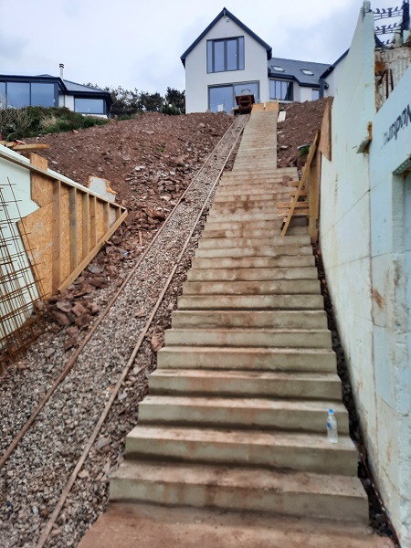
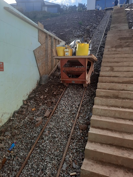
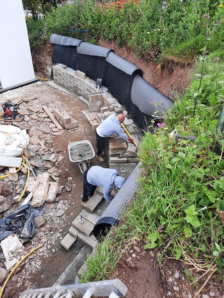
The pile of debris before our eyes stood at more than seven feet tall in the centre and it covered the whole area in front of us. ‘So, where is all the stone?’ we asked. ‘Oh! it’s definitely under there….. somewhere, or at least it was the last time we looked’ they said. We knew that we had to retain the excavated curved bank which stood over three and half metres tall at the highest point in the centre and tapered down slightly on either side. It was impossible to start any work here at this stage due to all the work going on with the house build so we arranged a further visit to discuss a basic design, access, start dates and way forward. We were assured that when we did finally start that all of the excess builders mess would be cleared away and decent access made available. Due to where the house was actually built, and being so high up from the road, access was one of our main concerns, not only for getting tools up, but all the tons of materials and additional equipment required to build this wall. Luckily for us the site had an inclined elevator, a form of cable railway that hauled a platform all the way up the steep gradient to the house. So, our first day on site in late May, we got to test that out by getting all our gear up.
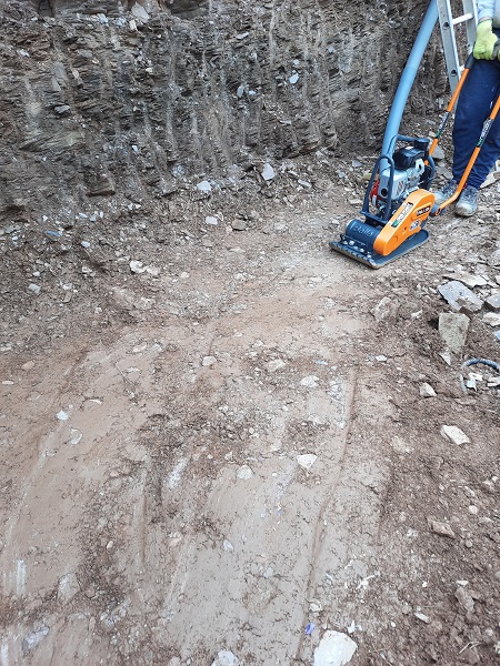
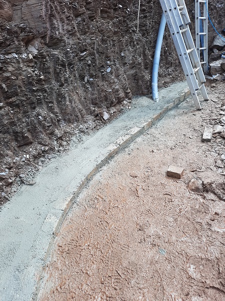
It was decided from the start that no foundations were going to be required for the new wall. The excavation had all ready been taken down to the solid bedrock and we were going to build straight on top of this. Our first task was to scrape away any loose material on top of the bedrock and give it a good going over with a plate compactor forming a solid and fairly level base.
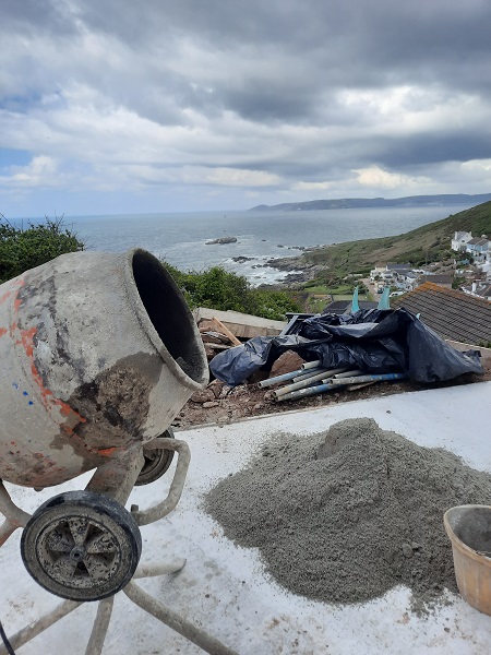
Next the mixer was set up on the concrete base at the front of the house with views to die for, and we were going to be here for the next five months or so.
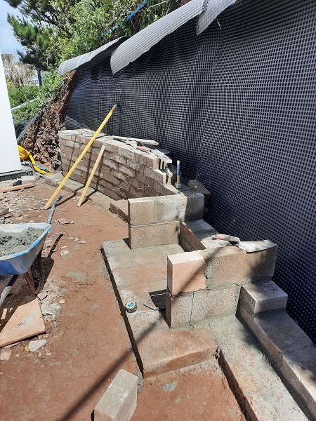
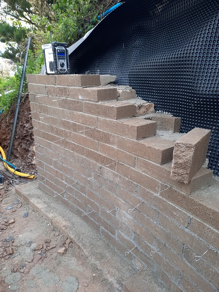
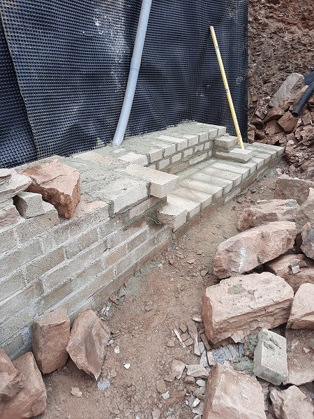
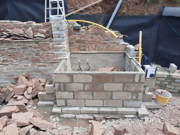
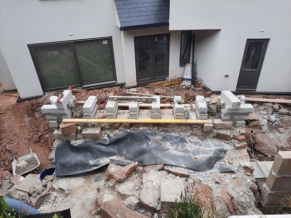
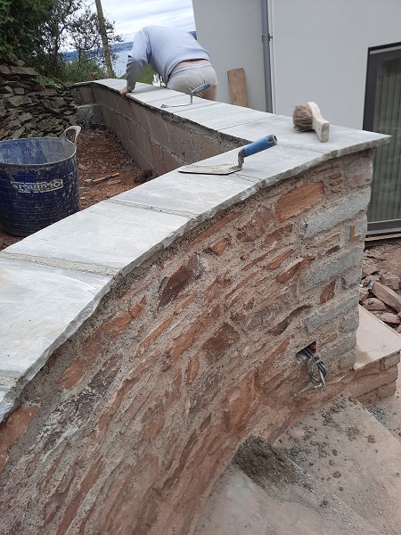
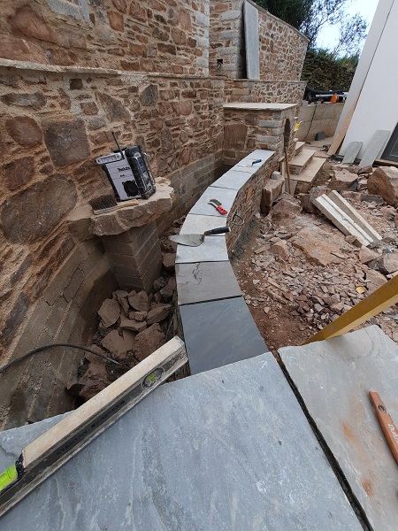
The new wall was going to be built up tight against the existing bank using concrete block as the inner core and faced off in the natural stone which had been dug out during the excavations. The first gauge of mortar was mixed up and we began laying down the first blocks setting out our initial baseline curve for the wall. This line was set in by eye to give a nice gentle curve following the bank and was set in level to become our datum.
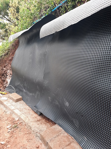
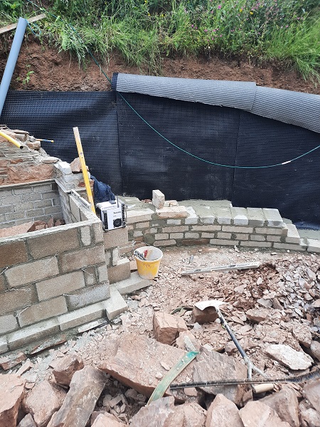
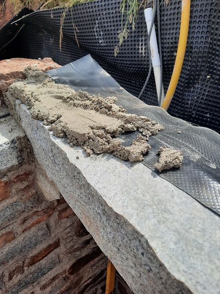
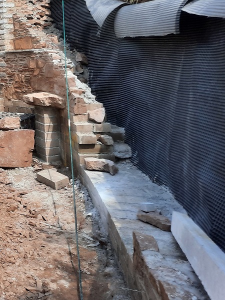
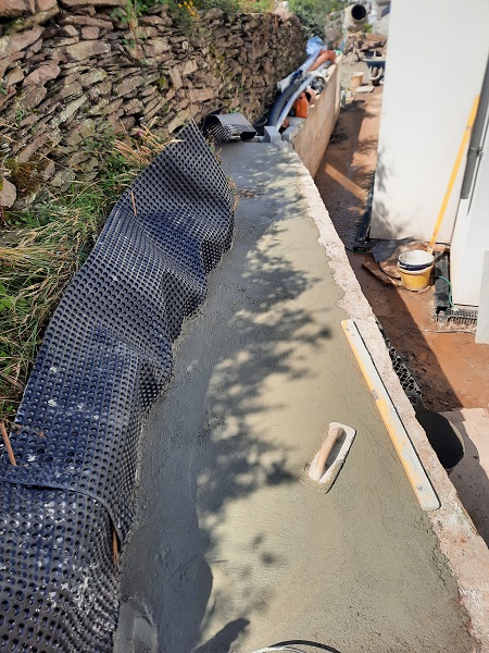
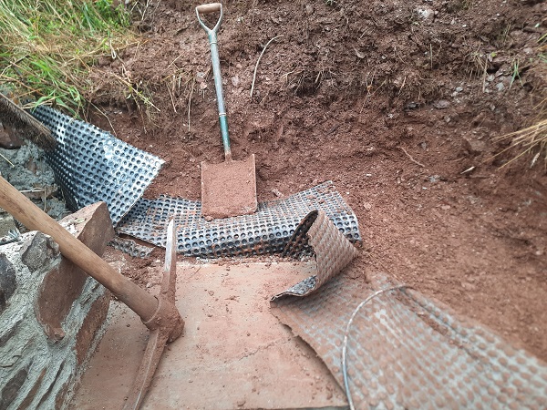
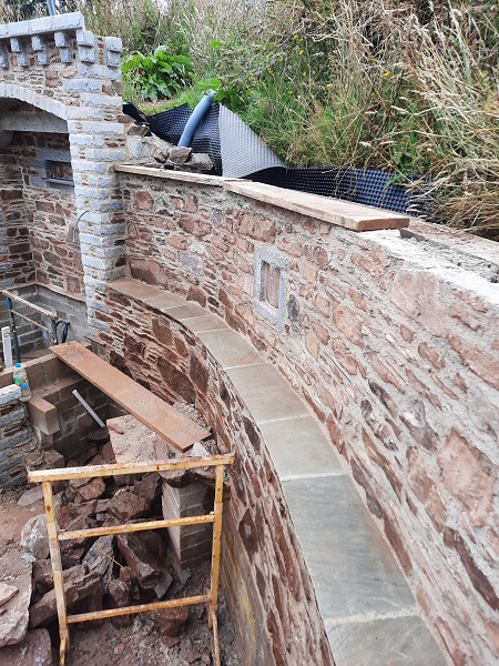
Some sections of the finished retaining wall, in places, would eventually be as much as two metres away from the bank and all the setting out could now be measured off of this baseline datum curve as the work proceeded, either behind the curve line or in front of it. In essence, if measured correctly everything would follow the same curve and could also be built level at the same time. There was also a new drainage channel that was set in around the house and this helped to determined our finished floor levels. But before we carried on building the wall a plastic ‘Geotextile’ membrane was fixed against the bank. This would prevent any damp, moisture or active running water travelling from the bank and through to the masonry. Any potential water accumulation behind the wall could only go straight down to its base, which at this stage was well below the finished ground levels that would be put in place when the wall was completed. A membrane like this would last at least a hundred years or so and for the relatively cheap cost of it, it really was a no brainer to not put it in at this stage of the work. There had been some periods of prolonged heavy rainfall prior to us starting work on site, but despite all this there was no evidence of any water seeping through the bank itself. The membrane was put in just to be on the safe side.
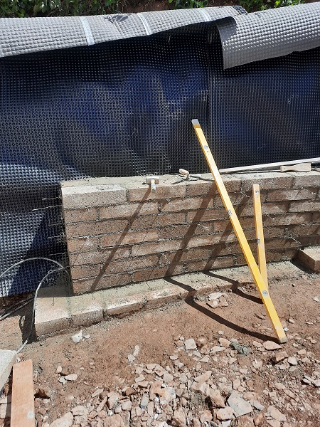
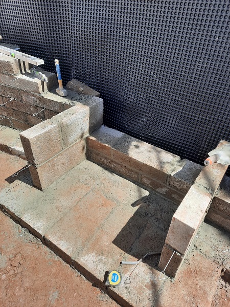
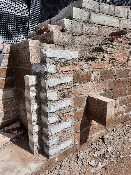
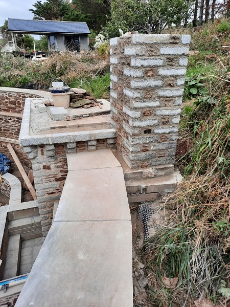
Now that the membrane was in position we could carry on with the blockwork. Although we had a rough idea of where we were going with this, we didn’t have any dimensioned drawings or plans showing the finer details and all we did have was a few rough sketches which we had ran by the clients. This was going to be one of those jobs where we more or less made it up as we went along making sure everything worked together as a whole. The new water feature that was going to be incorporated into the wall had to be the central feature, and the flight of steps that were needed to take you up to the higher ground behind the wall could only be built to the right of the water feature and we couldn’t even get access to that part of the wall yet because there was a mountain of stone piled up against the bank. So that meant the new built in fireplace come barbeque had to go to the left of the water feature which we soon got to work setting out the blockwork to accommodate that.
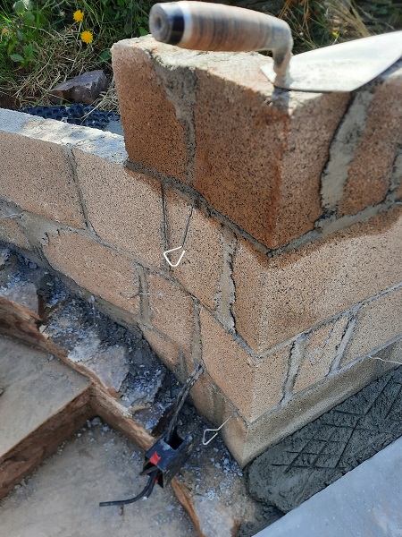
Stainless steel ties were built into the blockwork and this eventually would tie in the new stonework.
Once completed the fireplace come barbeque would have a built-in cupboard underneath the grill to store charcoal, fuel and anything else required for a decent barbeque.
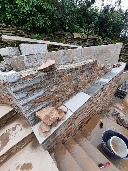
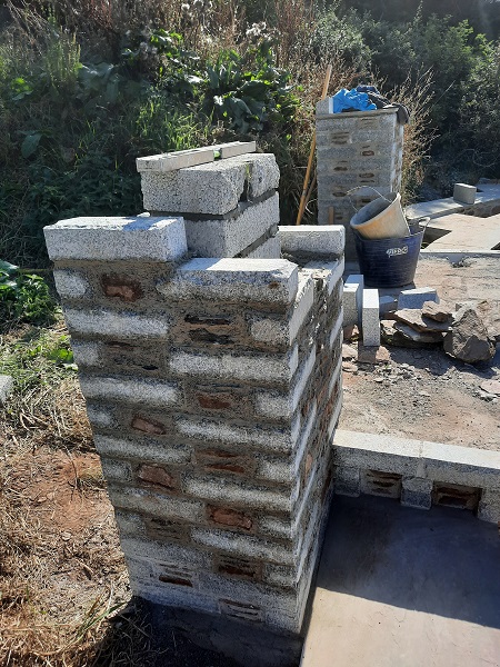
In total we were going to use in the region of two thousand concrete blocks or more in the construction of this wall and the blockwork was built solidly against the geotextile membrane using ‘English’ bond, the strongest bond of all. After getting the blockwork up to a certain height we were ready to start the stonework, and the pile of stone wasn’t going anywhere unless we used it.
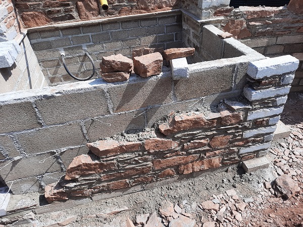
Although the stone on site wasn’t bad….it wasn’t brilliant either. What had been dug out of the ground during the initial build consisted of a local ‘Mudstone’ which first started its composition millions of years ago. With hues of dark reds, browns and purples it’s rich in the minerals and iron oxide known as ‘Hematite’ that give it its colours which was why early 19th century texts labelled this period ‘The Old Red Age’. These slates, sandstones, volcanics and mudstones are types of rocks that form large parts of Devon. They date from a geological period now more commonly known as the Devonian period and are the oldest rock formations found in Devon, formed about 400 million years ago when Devon was under the sea, which was surprising really when you could see just how high up we were from sea level, but we guess a lot of changes can happen over 400 million years. This variation of stone is found in South Devon from Torbay to Plymouth, and also on Exmoor in North Devon. Devon is unique as it is the only British county to give its name to be used and recognised worldwide as a geological time period and system of rocks, and Devonian age rocks are found in many other countries across the world. Great deposits of rock were formed during the Devonian times, in a period of continental collision and mountain building. This activity triggered lots of erosion, creating the sand and mud sediments to eventually become buried deep underground and ultimately transforming into rock. Devon, at that time, was at the centre of great dynamic activity which created the interesting variety of sedimentary rocks that we can find today, including slate, sandstone, limestone, volcanic, mudstone and schist. Life was fairly primitive in the Devonian period as this was the time before the dinosaur came into existence and so the first fossil records in Devon record fish, corals and other sea life. Also it is sometimes called the ‘Age of Fish’ because of the diverse, abundance, and in some cases, bizarre types of creatures that swam our Devonian seas. Life was also well underway in its colonization of the land as the first vertebrates were also starting to appear during this geological era and gave rise to the first ‘Labyrinthodonts’, which was a transitional form between fish and amphibian.
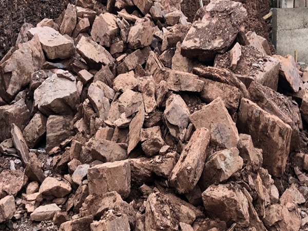
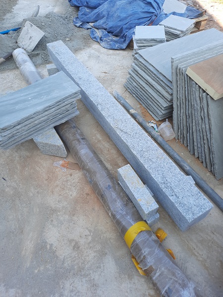
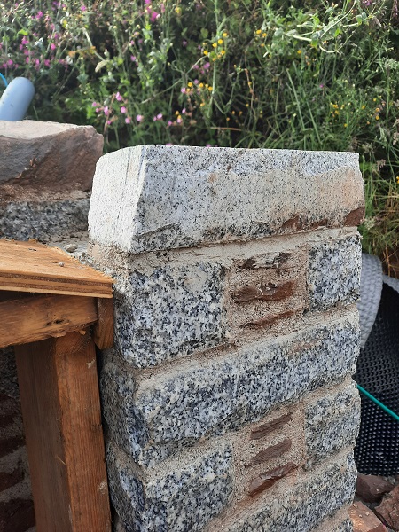
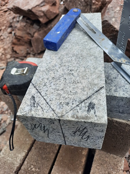
However, as interesting as it all this may sound, the main problem we had here was the fact that none of the stones were suitable for use as quoins, certainly not in the quantities we required, and we were going to need a load of quoins for this job. We have our own stone bench saw, but to spend time cutting all the stone for the quoins would not of been cost effective in this case and anyway, sawn cut edges never look natural. We offered an alternative option and it was decided that we would get some new stone for the quoins and a silver-grey granite was chosen by the clients to contrast with the stone already on site.
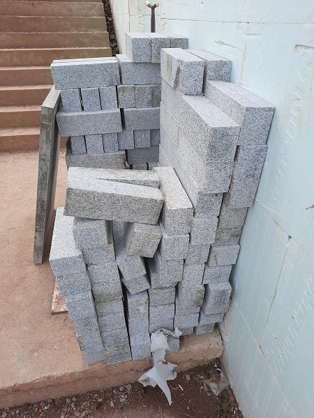
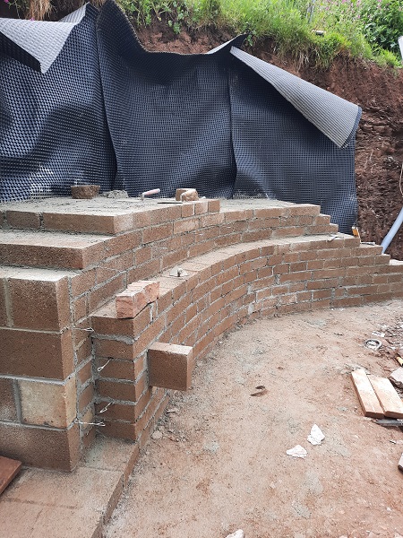
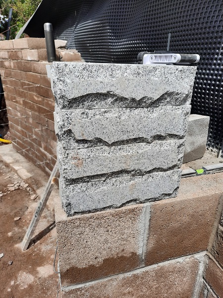
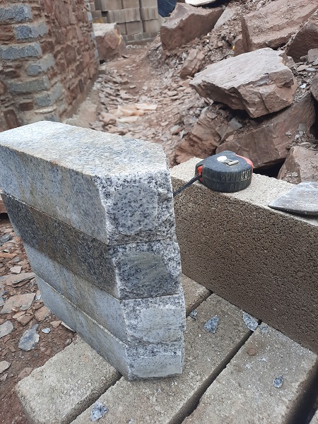
The new quoins in question were twelve inches (300mm) by four inches (100mm) by three inches (75mm) and all of it had a sawn face, which again doesn’t look very pleasing when built in the wall. That wasn’t going to be a problem though because we dressed all the cut faces that would be seen in the wall with a tungsten ‘Pitcher’ which takes off the sawn edges leaving what is known a a ‘Rusticated’ face. We would use this granite not only for the quoins, but also for all the other finer details we had in mind for the project.
Now that we had our quoins, we started to build up the new stonework and this retaining wall, for sure, was going to look stunning once it was completed. All the new stonework was going to be built using N.H.L.5, a natural lime which we gauged our mortar at three parts coarse silver sand and one part lime. N.H.L5 is more durable for use as a lime mortar which is why it’s recommended for use in coastal environments and the sea shore here was literally a three minute walk down the road.
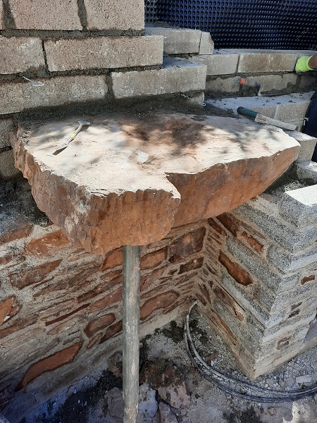
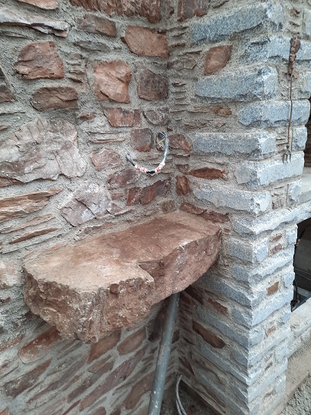
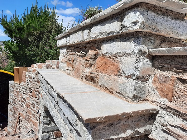
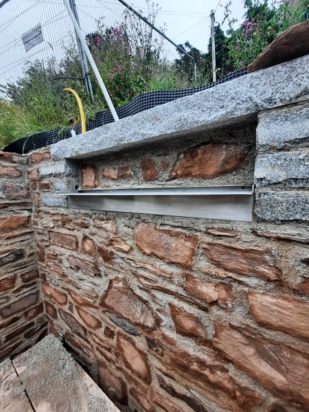
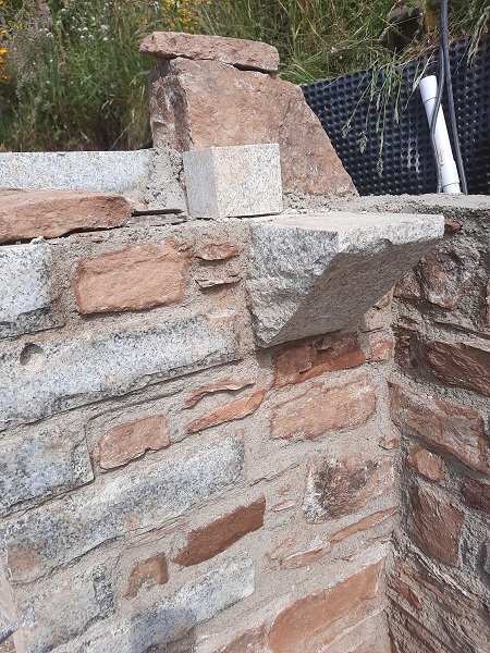
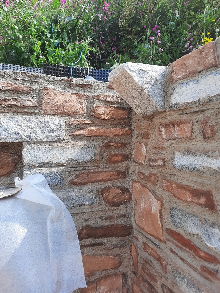
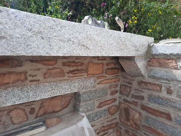
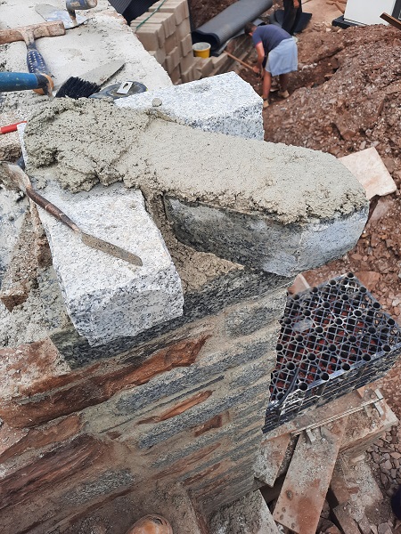
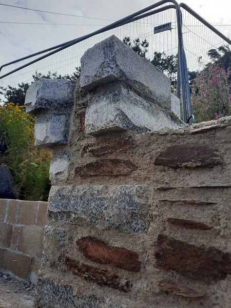
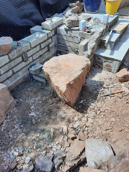
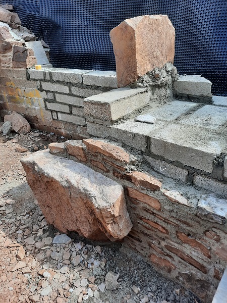
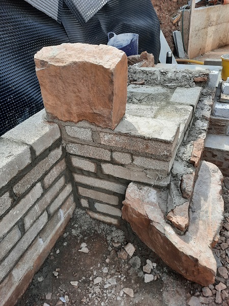
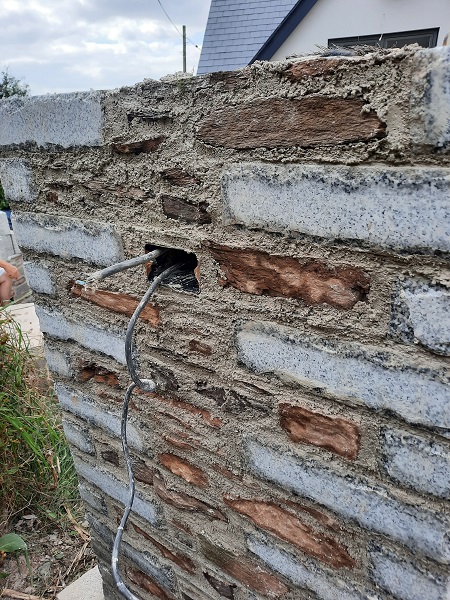
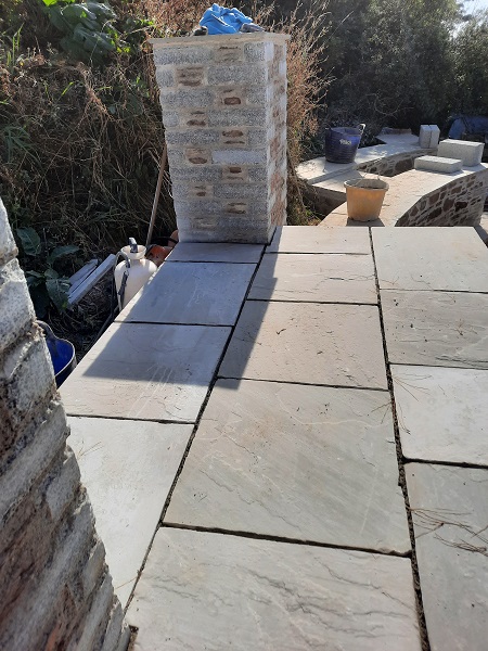
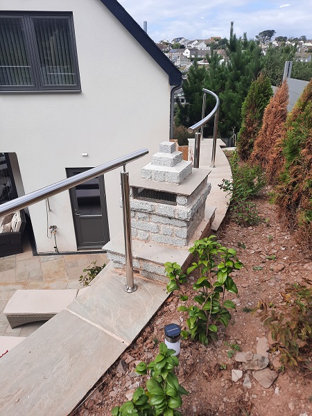
In amongst the pile of stone we came across some rather large lumps of rock and since we were going to make this up as we went along we thought this particular piece, which was about eight inches (200mm) thick, would make a nice additional feature. We set it into the wall next to the fireplace which cantilevered out to form a small shelf…..perfect for putting a pint of beer down whilst cooking on the barbeque.
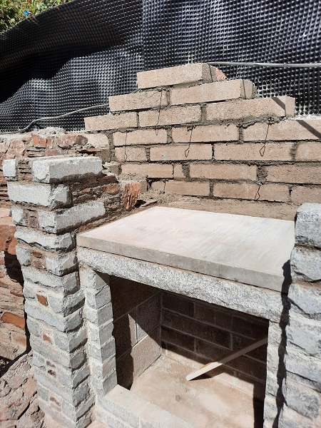
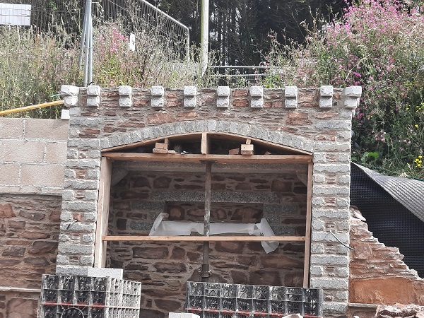
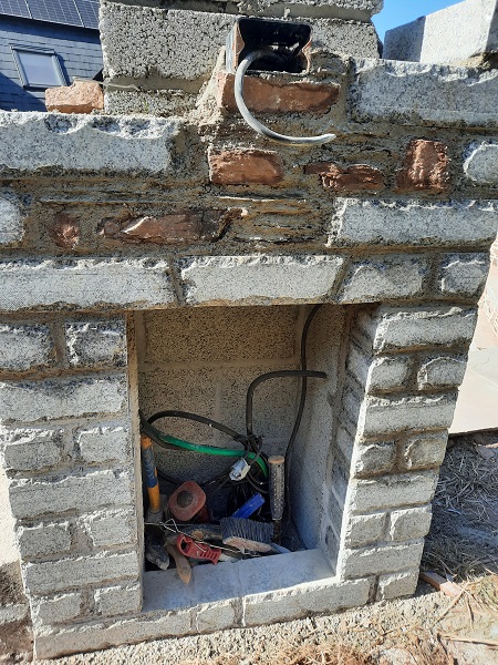
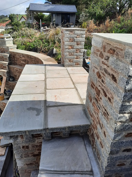
The cupboard under the fireplace was up to height and now it was time to set in a granite lintel with a two inch (50mm) thick concrete slab on top which would form the roof of the cupboard and the base of the fireplace.
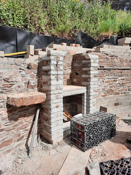
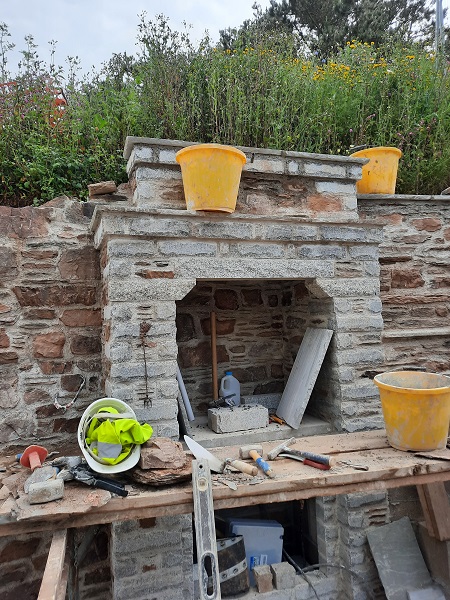
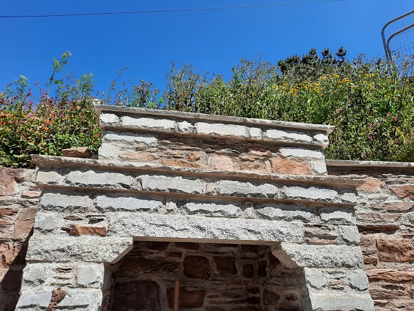
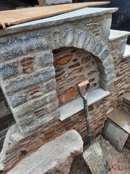
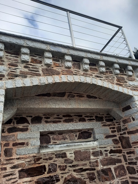
The opening for the fireplace was continued up with stone up to lintel height and here at this level we set in a couple of splayed corbels to form a feature known as a ‘Jack’ arch. A Jack arch is a structural element in masonry construction that provides support above openings in the masonry. Alternate names are ‘Flat’ arch, ‘Straight’ arch, ‘Shouldered’ arch and sometimes it’s even called a ‘Castle’ arch as it is often been used in the construction of many castles. Unlike regular arches, jack arches are not semi-circular in form. Instead, they are flat in profile and are used under the same circumstances as lintels. Unlike lintels, which are subject to bending stress, jack arches are composed of individual masonry elements cut or formed efficiently using the compressive strength of the masonry in the same manner as a regular arch. Like regular arches, jack arches require a mass of masonry on either side to absorb the considerable lateral thrust created by the jack arch. Jack arches have the advantage of being constructed from relatively small pieces of masonry that can be handled by individuals, as opposed to some lintels which can be very heavy to lift into position.
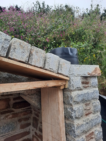
When the lintel for the jack arch was in place we built a course of granite over the top of this with another course of granite on top of that again that corbelled out by about one inch (25mm). This was finally capped off with a silver-grey Indian sandstone to form a coping which also projected out from the corbel underneath by about one inch (25mm) thus incorporating a nice little detail within the stonework and these details don’t really add any additional costs to build especially if you have the right materials to hand in the first place.
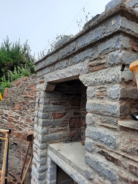
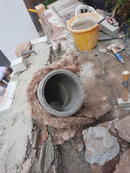
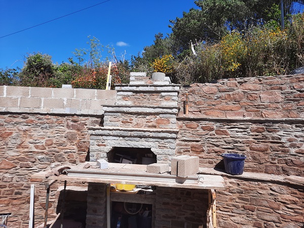
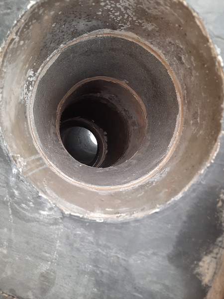
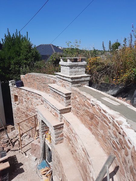
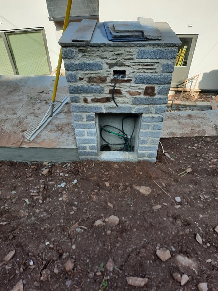
Because a fire or a barbeque was at some point going to be burning in this recess, our next job was to set out the chimney along with a flue for all the smoke to go up it. The opening at the top had to be reduced to take a ten inch (250mm) diameter flue and this was achieved using concrete lintels and natural roof slate that had the correct diameter hole cut into it for the flue.
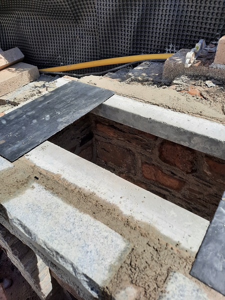
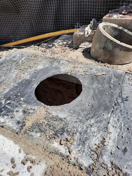
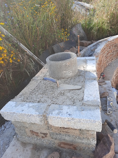
The first section of flue was positioned over the hole cut into the slate and the flue was wrapped in ‘Rockwool’ which is a fireproof insulation to allow for heat expansion otherwise the masonry could crack around the flue. The flue was set in place by casting a four inch (100mm) thick concrete slab around it on top of the slate. Slate doesn’t catch fire and that is why we used it as a shuttering to hold the concrete in place while it set and should the thin slate deteriorate through heat exposure in the future, at least the concrete above would not.
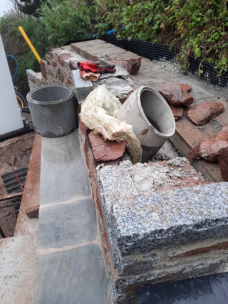
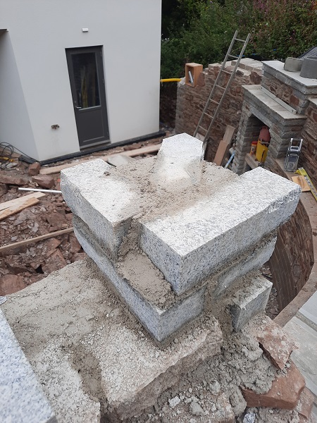
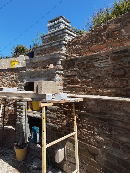
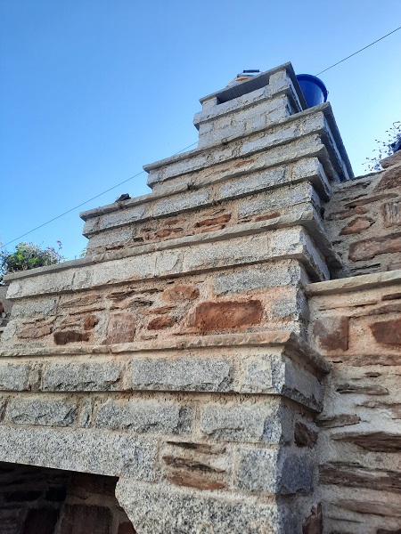
As we continued higher with the chimney we stepped it back in from the face of the fireplace by about twelve inches (300mm) which also enabled us to build a curve in the flue using offset sections and this can help deter any downdraft.
As well as stepping the chimney back from the face of the fireplace, we also stepped back the left hand side by twelve inches (300mm) whilst keeping the right hand side upright with that side of the fireplace. When completed up to the final height the chimney would form a quirky feature as if leaning to one side.
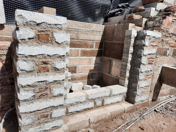
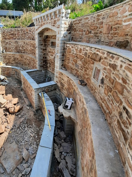
There was still much more to do on this section of wall and by now we had a good idea of where we were going with it, but for now we decided to leave this area and start setting out the next part of the wall….the middle section….which involved the central water feature. We set out the blockwork for this following the same curve line for the bank we were retaining.
We wanted to set the water feature back from the main face of the wall to give more depth in its appearance. Once we got the blockwork up to the required height, stonework was put in place which would form the reveals of the new water feature. A course of the silver-grey Indian sandstone was built in first at the back of the water feature and this would eventually continue out in front to line up with the wall copings that was planned to go around the reservoir forming the new pond. During the course of the works we also built in conduits which would give access for any electric cables to feed the water pump and any lighting.
More blockwork was then added in front to form the walls of the pond which had stainless steel ties built into it in preparation to take stonework.
We also continued the blockwork around to the right of the water feature.
New stonework was then built up to face the blockwork around the pond.
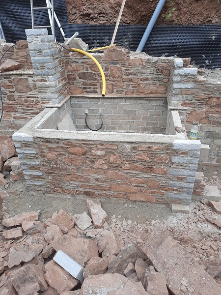
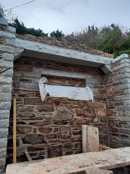
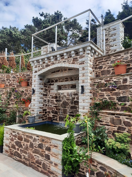
Once the stonework around the pond had hardened off we were able to set up some trestles within the pond area and the walls gave a solid base for us to span some scaffold planks across so we could build higher. The next thing to build into the back wall of the pond was a ‘Water Blade’, a precision made trough which is manufactured out of stainless steel. This creates a slit in the stonework above the water level of the pond which is connected to the water pump by means of an uplift hose. This water blade was set in about five foot (1500mm) above what would be the finished water level for the pond. Eventually when everything is connected up water is pumped up to the water blade creating a continuous glass-like sheet of cascading water. It also has colour changing L.E.D. lighting built in so that different colours of the waterfall can be achieved. The water blade used was three foot (900mm) in length and it is crucial to set this in absolutely level or the desired effect of the cascading water will not be achieved. We set in a new granite lintel above the water blade.
Because the back wall of the pond and its water blade was set back into the face of the retaining wall, we carried on up with the pillars on either side and in the meantime got a granite lintel prepared along with a couple of corbels.
The corbels were set into the sides of the pillars, in front of and, slightly higher than the opening for the water blade itself.
The granite lintel sat on protruding corbels to form another ‘Jack’ arch matching the one that was built into the barbeque. Each corbel was cut from a piece of granite about eighteen inches (450mm) long and roughly six inches (150mm) square and two thirds of the corbel is built into the wall.
A damp proof course (D.P.C.) is laid over the top of the lintel to close the gap between the back of the lintel and the face of the stonework behind and this will prevent water seeping down from above which can potentially cause unsightly stains directly under the lintel running down the face of the wall in the future.
Then, on top of the damp proof course, a very small amount of stonework was built on top of the lintel because an arch was the next feature to be built and this bit of stonework was going to be seen once the arch was complete.
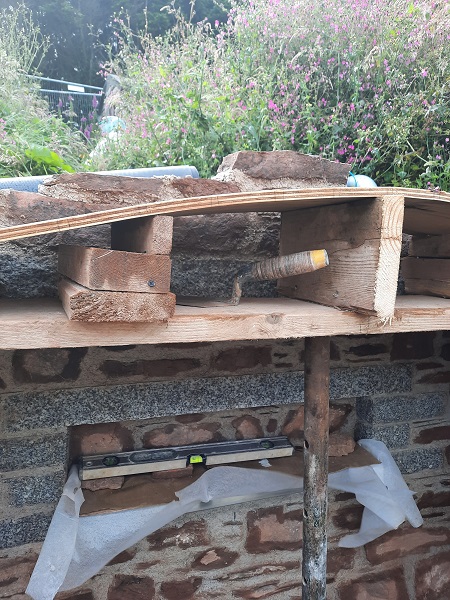
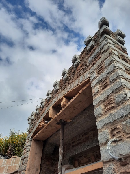
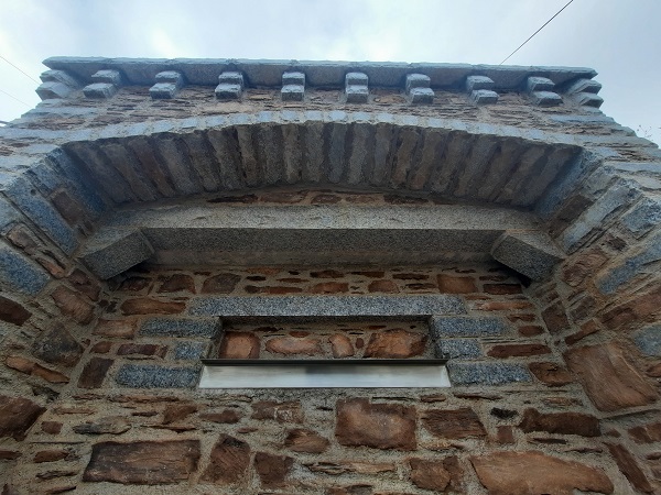
Now all that was set out it was time to make the timber ‘Centring’ for the arch and set it in position. A centring is a temporary support put in place to build the arch and once the arch is set the centring is removed. It is important to make sure that the centring is fully supported and firmly wedged into position with no movement whilst the arch is being constructed.
Once the centring is in place the ‘Skew backs’ can be made and these are cut from granite at ninety degrees to the centring so that the arch can start from this point. A skew back is set in on each pillar either side of the arch.
The granite to form the arch is first laid out dry along the top of the centring and each stone spread out so that every joint is evenly spaced which is then marked out in pencil along the edge of the centring for reference.
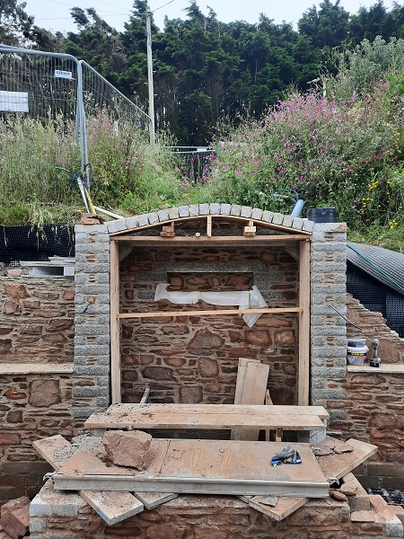
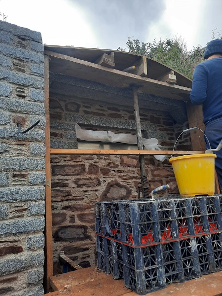
The granite arch was built in and then the stonework levelled above to bring it up to height.
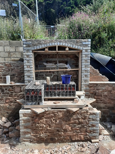
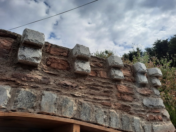
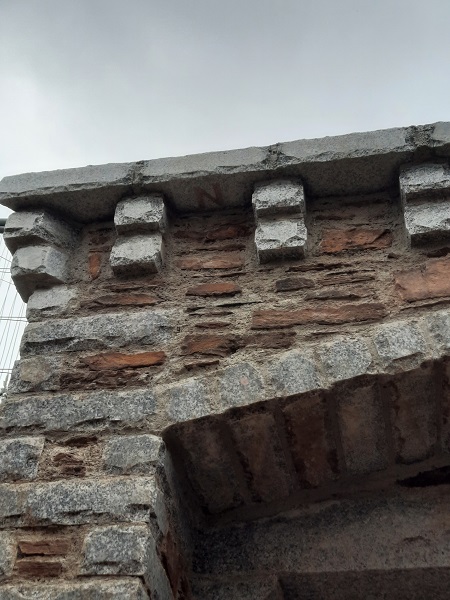
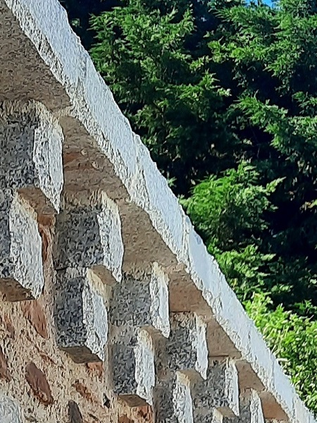
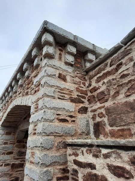
On top of this we were going to form an architectural feature that you would normally find on a Medieval castle or fortification. This feature consists of a series of corbels that support a parapet above and are know as ‘Machicolations’. In order to proceed we first had to cut and shape the corbels for each corner.
Once these were ready each corner was set into place. The first corner corbel projected out from the face of the wall by about one and a half inches (40mm).
On top of this we set in a further corbel which also projected out the same amount from the corbel directly below it.
Now that the two corners were in place we strung a line from end to end and set in the rest rest of the corbelling to follow suit.
Stonework was built in between the corbels.
On top of this we laid another course of granite forming the top edge of the parapet. This course ended up about four inches (100mm) out from the face of the stonework below.
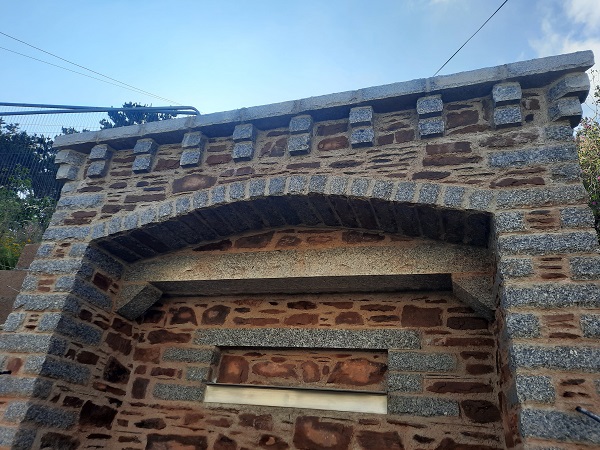
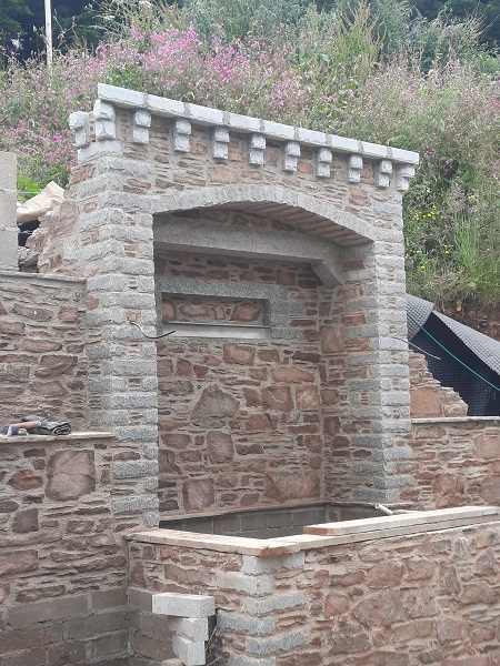
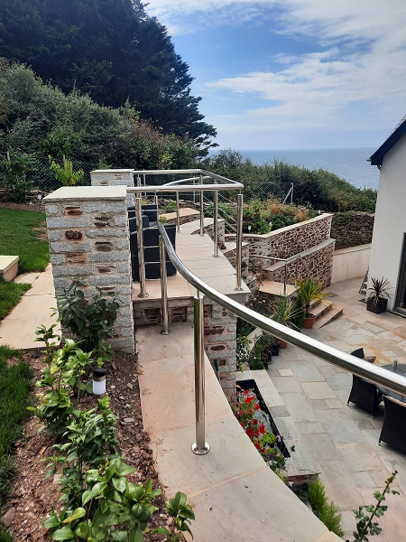
The returns on the machicolations would have to wait for now until the wall was up higher. Eventually the area on top of the parapet would be paved using silver-grey Indian sandstone to create a viewing platform as this was an advantage point looking out across the ocean, and it also overlooked the pond and courtyard below. Stainless steel railings would also be fitted around the parapet on completion for the aspect of safety.
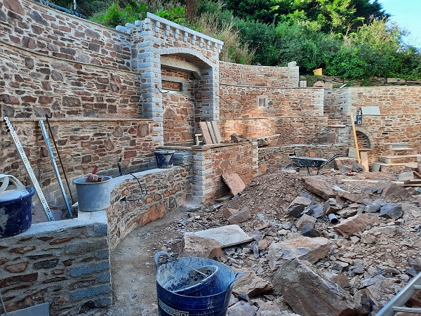
On fortifications centuries ago the spaces between the corbels would have been left open for defensive purposes where arrows could be fired through or stones and hot tar could be dropped down on to the enemies below at such times during a siege or when the castle was under attack. But for now we had gone as far as we could on the water feature and had to think about carrying on with the retaining wall around to where the new steps were going to be built. The only problem here was that a great deal of stone was piled up against the bank where we needed to build and the only way to get that out of the way was to bring in a mini digger to make us some room.
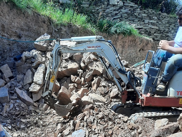
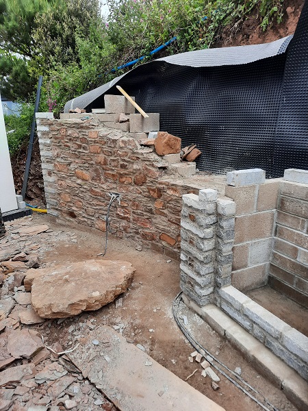
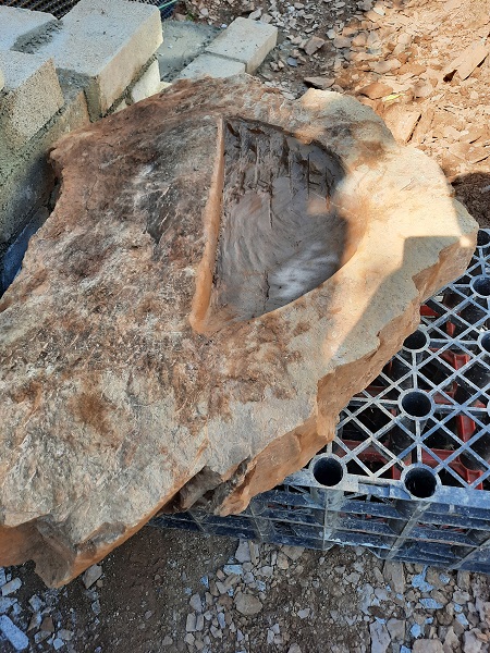
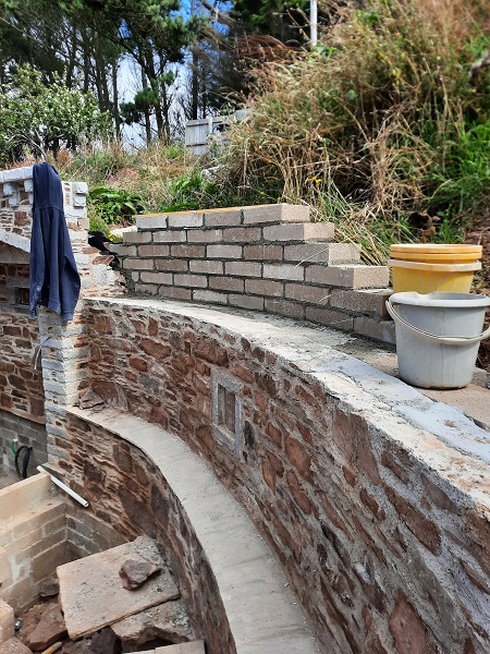
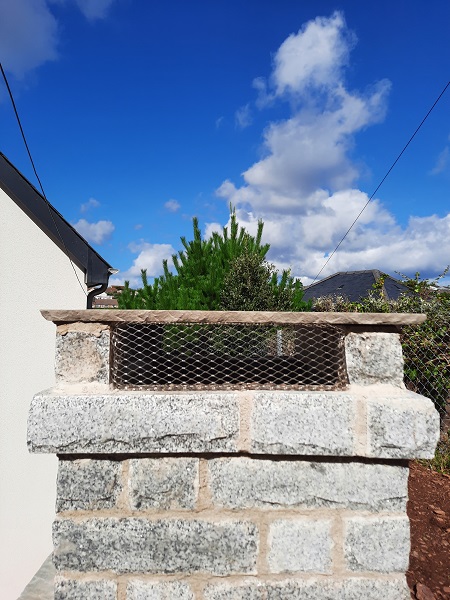
This wall was going to be full of surprises and interesting details so whilst the stone was being cleared away for us we came up with an idea to create another feature in the form of a small bird bath which we could build into the face of the wall. There were some sizable chunks of stone to choose from in the pile so we pulled out a piece suitable for the job which was roughly six inches (150mm) thick. This was marked out and a shallow dish carved into it to hold water.
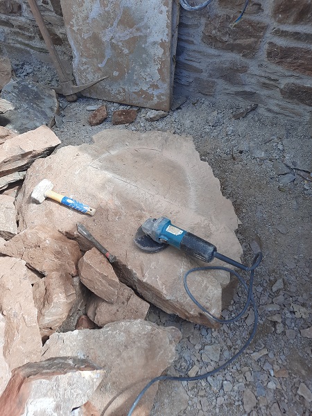
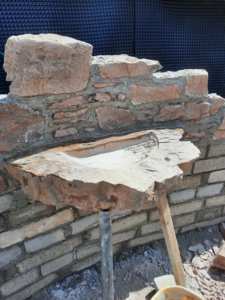
Once all the stone had been cleared away from the bank the bird bath was then set into the wall to the right of the water feature. Stonework was built over the top of it which kept the bird bath in place.
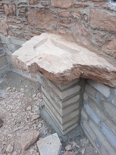
We also built a block pier underneath it for added strength. The blockwork would not be seen as a planter was planned to be built in front of it later and the earth used to fill the planter would be level with the bottom of the bird bath.
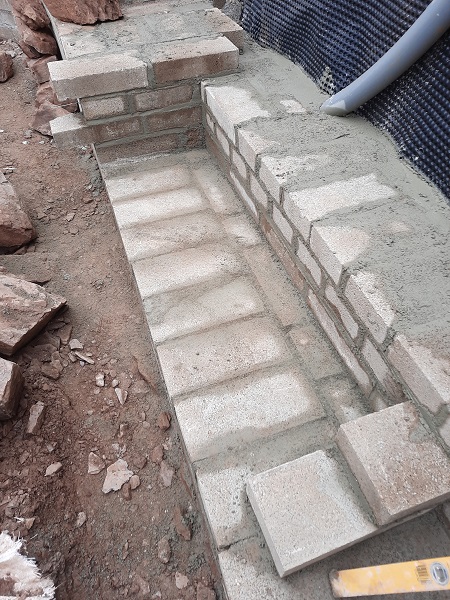
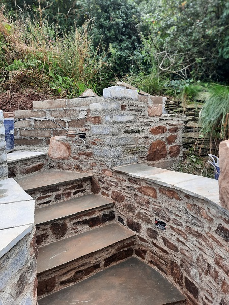
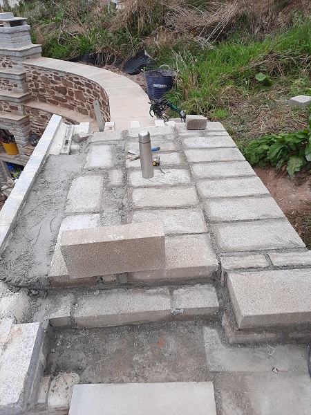
Now that the mini digger had cleared space for us we carried on around with the curved blockwork to retain the bank. We also had to think about how and where the new steps were going to be built.
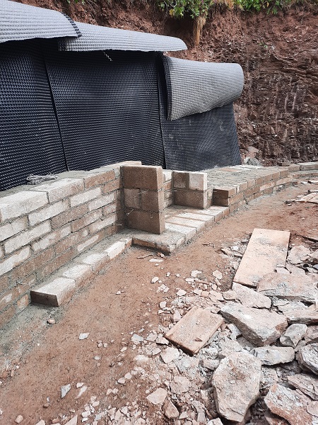
And once we got our heads around the design, we plate compacted the ground, laid down a concrete slab foundation and set out the base for the new steps. It was critical to get the base for these steps in the right place, but even more important to get the correct level to work with the finished floor levels of the courtyard paving which would be laid at a later date.
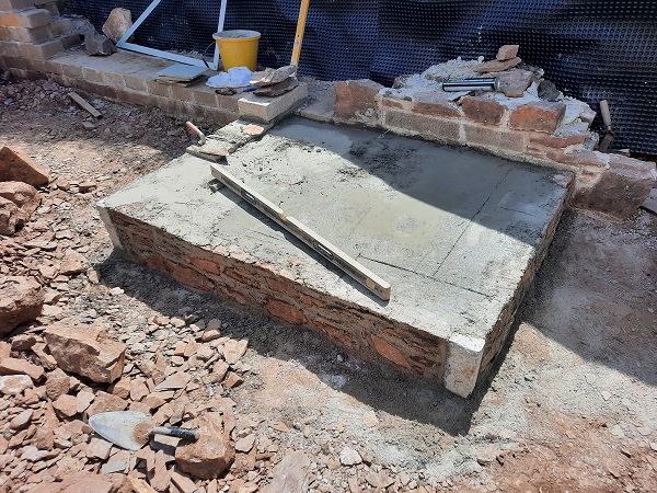
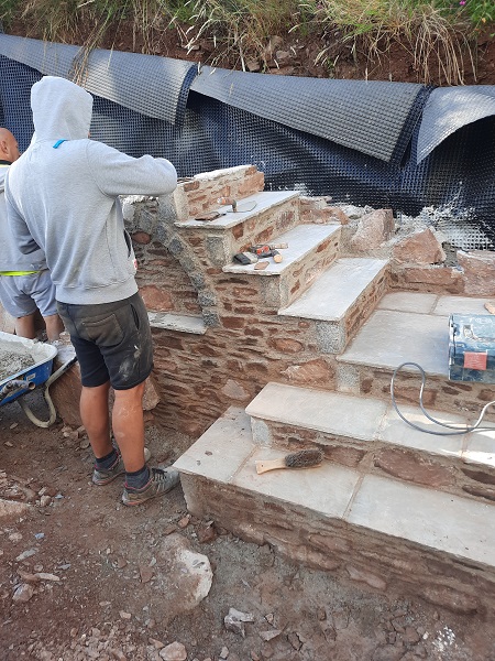
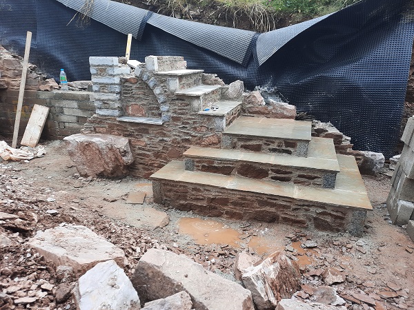
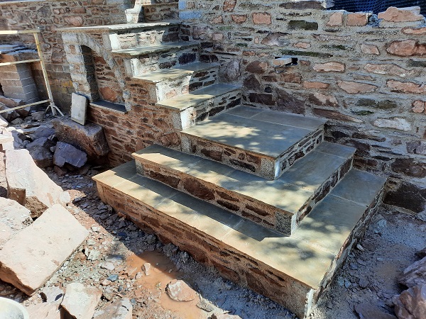
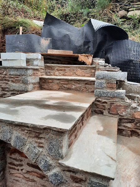
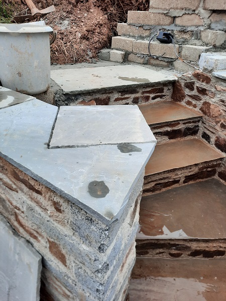
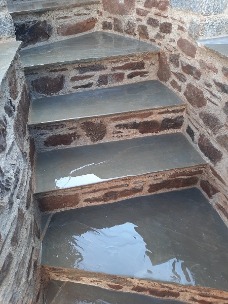
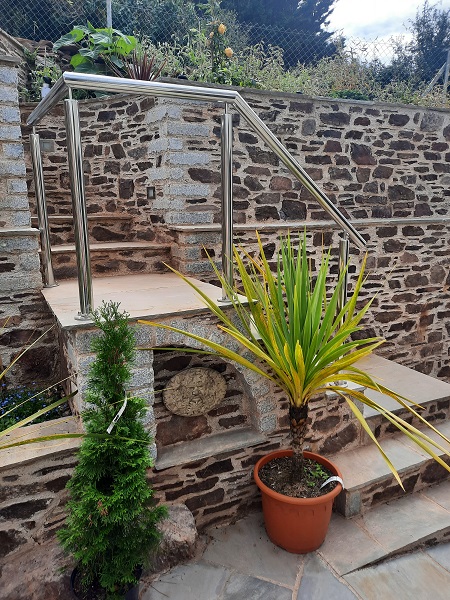
The risers for the steps were built using the natural stone whilst silver-grey Indian sandstone was used for the treads.
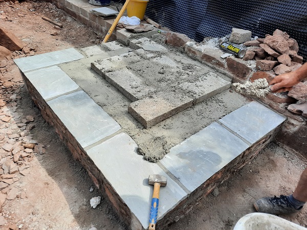
These steps were to be stepped on two sides and we added another two steps to form the first landing on top , we also used dressed granite for the corner of the step risers. The entire steps were to be constructed as a solid mass of masonry.
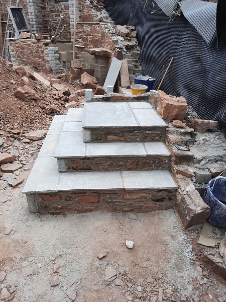
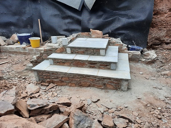
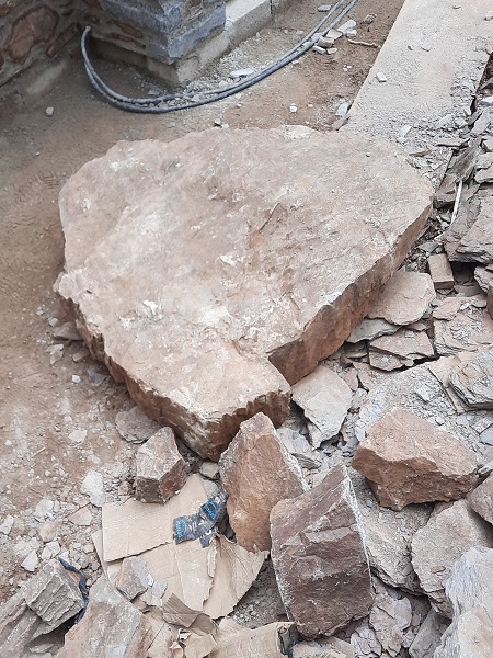
The steps needed to go higher and also extend to the left. There was a really big lump of of stone on site which would of been difficult to get rid of, and a shame to break up, so we set it in the base to form the corner stone for the next stage of the steps.
From this we extend the base of the new steps with solid blockwork faced with natural stone. The large corner stone was set in about six inches (150mm) out from the face of the stonework which formed the wall to the side of the steps and created a small ledge.
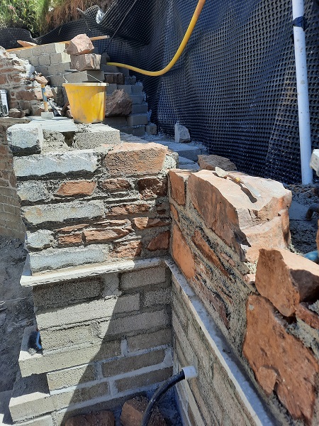
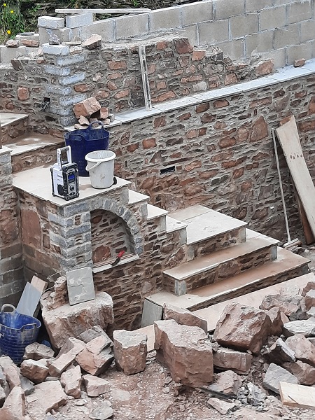
With the blockwork now faced with stone we took the steps higher and built in a quadrant shaped arch into the side of the stonework to create a niche with a sandstone sill.
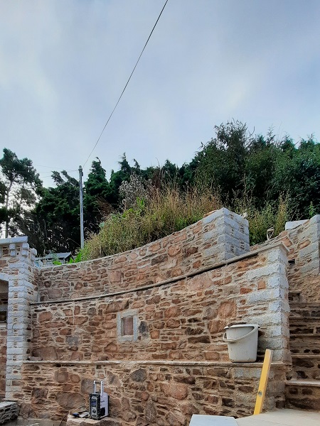
Having formed another four sets of steps taking you up to the second landing above the arched niche, that was now up to level so we concentrated on finishing the final curve of stonework retaining the bank.
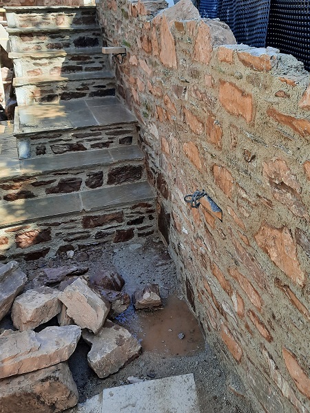
And the stonework to the left of the steps going back towards the bird bath and water feature was also built up to the required level which was all built in solid against the bank.

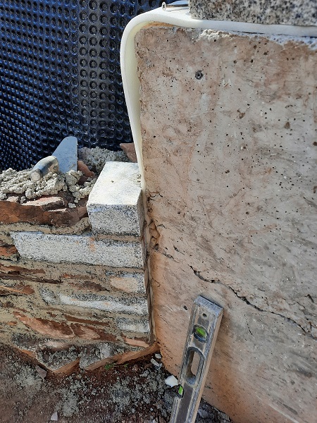
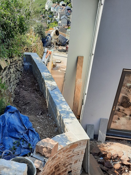
The very far right hand side of the stone retaining wall lined up with a section of reinforced cast concrete retaining wall that ran down the side of the house. Here we set in some stainless steel ‘Slip’ ties that were drilled into the concrete and fixed in place with epoxy resin and formed an expansion joint between the concrete and the new stonework. Slip ties allow for any movement within the expansion joint. We kept the face of stonework out proud from the concrete by about an inch (25mm) as the concrete would be rendered with a decorative render at a later date and this would give an edge to render up to.
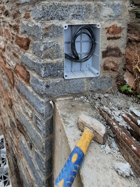
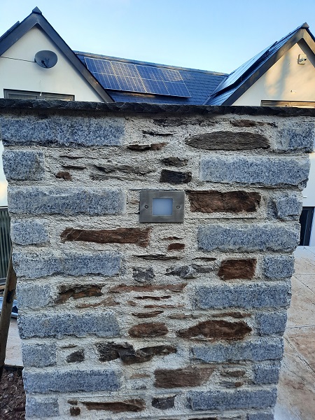
The retaining wall was then brought up to height between the concrete wall and the top landing of the new steps. Electrical boxes to house switches and armoured cable were built into this section of wall to feed the downlighters that would light up the steps at night.
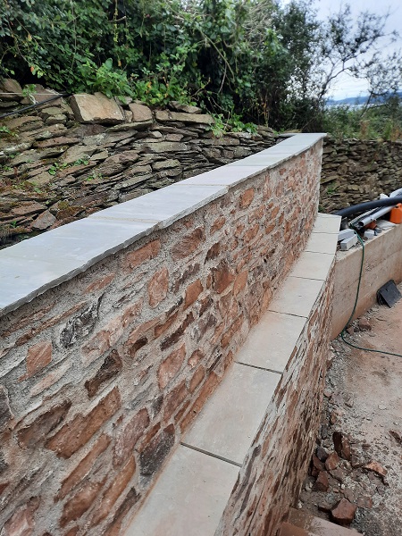
Above us is an old field drystone wall, a few feet behind the new wall, and that formed the boundary of the new property. The land on the other side of the boundary belongs to the National Trust and part of the South Devon coastal path runs through it. We had to make sure that our new retaining wall protected the old drystone wall from subsidence.
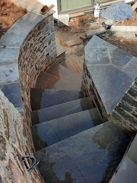
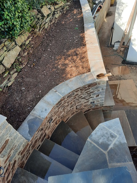
The initial design concept for the steps was to just keep going up as we were, following the curve of the retaining wall until we got to the top. However, it soon became apparent that to build that amount of masonry against the new wall which would hold up the steps was going to be vast. Firstly it meant that the bird bath would be lost. Secondly there would be no raised flower bed as the steps would take up that area, and thirdly, after working out the goings and the rises for the steps, the steps at the top would conflict with the top of the water feature, and we didn’t want that. Also, even if it did all work to levels, the steps would look too bulky and not in ratio with the rest of the wall. Another option we toyed with was to build a set of cantilevered steps using granite kerbs leading up from the second landing to form what would look like a set of floating steps built into the side of the wall. This meant that the bird bath could stay underneath and also the raised planter could be built. Although the cantilevered idea would of looked great, and it was achievable, the logistics of actually getting the heavy granite kerbs for the steps up from the road, onto the platform hoist, taken around the back of the house and then lifting them into their final positions was going to take a huge amount of effort. As mentioned, this job had no plans or drawings and it was a case of building it as we went making sure everything worked as a whole, so this wasn’t going to be a problem. Eventually it was agreed that we would turn the steps ninety degrees from the second landing so the steps would now go through the retaining wall. They would then curve up around following the back edge of the wall until they reached the top. More importantly this kept the steps well away from the water feature as they would now be hidden behind the wall and proved to be the best option in the end. This was the next part of the wall we started to set out and we built in the next two steps above the landing to lead us up and around the back of the wall.
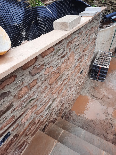
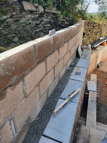
Before we could go any further we had to raise up the walls that would form the sides of the steps. On top of the wall to the right of the steps where we had retained the old drystone wall, we built a four inch (100mm) thick block wall, setting it back from the line of the wall below by sixteen inches (400mm) to form a ledge. The blockwork had ties built in so we could face it with natural stone. Once completed this section of wall would be backfilled in behind with soil to form a flower bed. This was also going to be the final height of the wall for this area.
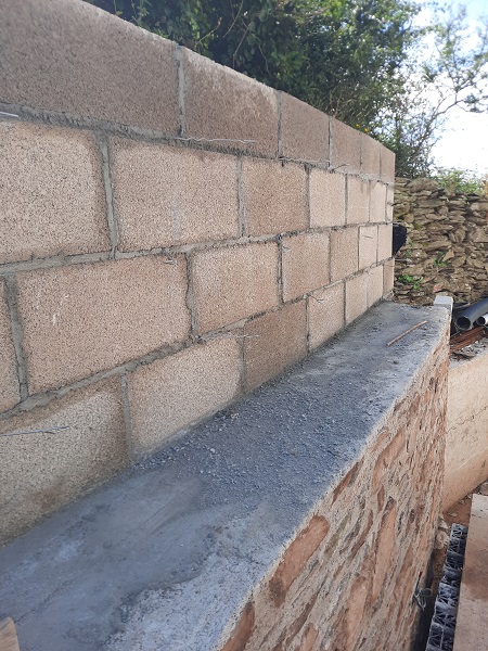
Silver-grey Indian sandstone was laid along the ledge to form a sill.
This block wall would also curve up around to form the right hand wall for the steps where we also built in the electrics for the step lighting as we went.
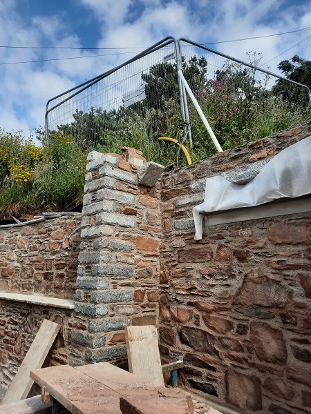
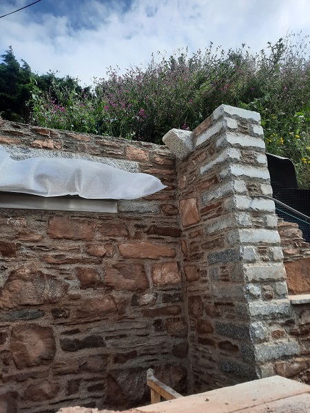
Once the blockwork had set it was then faced off with four inches (100mm) of natural stone using the dressed granite for quoins.
This section of wall was then brought up to its final height forming the planted area in behind.
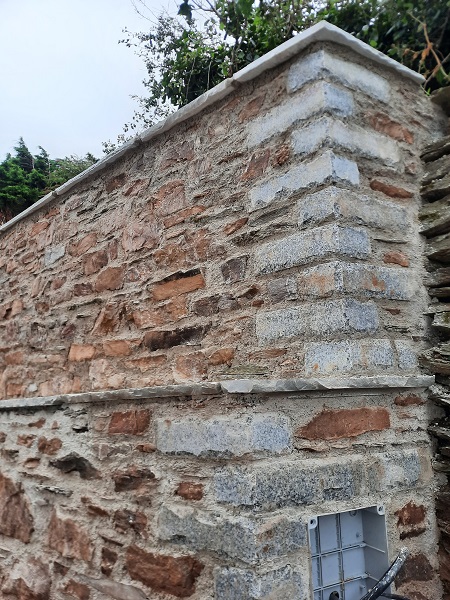
A coping using the silver-grey Indian sandstone was laid on top.
Because it had not been dug out during the initial machine excavations, we had to hand dig the ground in behind the back of the wall to accommodate the new steps as we went.
As we were digging out the ground we struck something buried in the soil.
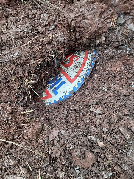
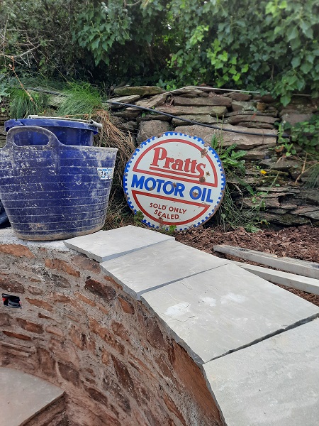
At first we had no idea what it was and with a bit more digging it turned out we had uncovered an old twenty-four inch (600mm) diameter enamel sign advertising ‘Pratts Motor Oil‘ which dated back from the 1930’s and considering it had been in the ground for years, remarkably, it was still in a very good condition, and the design on the reverse side of this sign was exactly the same.
Before we could go any further with the steps we had to bring the retaining wall to the left hand side of the steps to the water feature up by another thirty inches (850mm). Part of the back of this section of wall would also form the left hand side wall for the steps as they continued up around. It was along this section of wall where another feature was built into it.
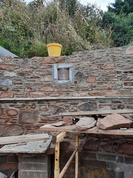
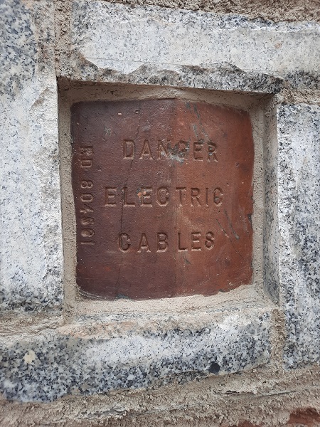
The land purchased for this new build project was originally owned by The Admiralty and formed part of what used to be H.M.S. Cambridge, a Royal Naval shore establishment in use between 1956 and 2001. Formerly named H.M. Gunnery School, Devonport, then Cambridge Gunnery School at Wembury. The site was called H.M.S. Cambridge after a ship of the same name, an 80-gun third-rate ship of the line that was used to train seamen in gunnery in Plymouth harbour from 1856. She was replaced by the first rate H.M.S. Windsor Castle and renamed H.M.S. Cambridge in 1869 before the gunnery school was moved onto land at the Plymouth naval barracks in 1907. This lasted until 1940 when a gunnery range used by the army and navy was opened at the old Wembury Point Holiday Camp which was named the Cambridge Gunnery School. In 1956 the school was commissioned as an independent shore establishment and was decommissioned on the 30th of March 2001. The site was purchased in 2006 by the National Trust, and the main installation, which included mounts for a range of standard naval guns, were demolished and cleared away, and the site returned to nature. The original mains electric cables which once supplied H.M.S. Cambridge with power ran underground on the site of the new build we were working on. Although the cables were disconnected and no longer live, there were loads of apex shaped ‘cover stones’ on site which originally would have been placed over the live cables that where buried here underground. This would give some warning to anyone excavating the ground that electric cables were underneath. The client asked us to build one of these ‘cover stones’ into the new wall framed with granite quoins to form this little feature.
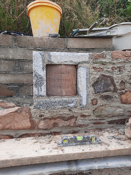
These ‘cover stones’ are made from clay and then fired in a kiln, much the same way as bricks are made, only these have a warning message stamped into it. The Registered Design Number RD 804561 is the same as that which is often stamped on similar electricity cable cover stones manufactured by the Callender Cable and Construction Company Ltd, of Erith in Falkirk, Scotland, and they also had a couple of premises in London. Founded by William Ormiston Callender after visiting asphalt deposits in Switzerland during a visit there in 1870 with the purpose of importing the asphalt and refining it for the many road making schemes taking place in London at that time. Along with the contracts awarded nationally, they also secured contracts overseas. In 1880 on a visit to Russia, William’s son, Thomas, saw that the opera house in St. Petersburg was lit by Jablochoff candles. To exploit the developing market for electric lighting, the company decided to turn the business towards the production of large-capacity insulated cables by insulating the cables with vulcanised bitumen for which they held the patent for.
Now that this section of wall was up to the next level, we turned our attention back to the steps bringing them up higher again.
The flower bed was filled up with topsoil finishing level with the base of the old drystone wall.
At the same time this section of steps were being built, the top section of the retaining wall was built back to the water feature. Blockwork was built first with stainless steel ties to take stonework.
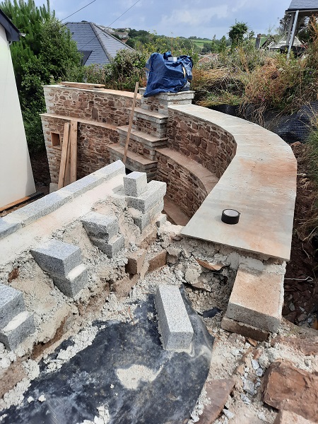
Then the blockwork was faced of with new stonework finally arriving at our finished height, giving full access to the higher level behind.
Indian sandstone was laid on the top of the wall to give a two foot (600mm) wide coping.
With this section of wall completed and with the coping on we were able to finish off the machicolated return to the top right hand side of the water feature.
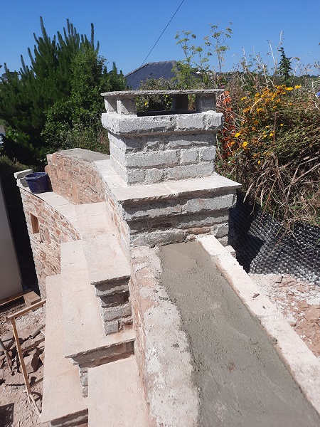
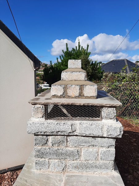
Our next task was to jump back onto the chimney for the B.B.Q. whilst continuing to step the chimney back into the wall as it went up. The top sections of the retaining wall on either side were brought up at the same time.
The finished height of the chimney would be higher than the top of the retaining wall either side. The flue was built up as the work proceeded.
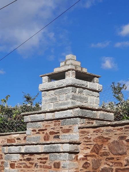
The chimney at the top finished off about eighteen inches (450mm) square with a slab of Indian sandstone on top. Any smoke would exit the chimney through the vents on all four sides underneath it.
Indian sandstone copings were laid on top of the wall to finish of the height on either side of the chimney.
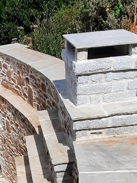
And stainless steel spark guards were fitted to all four vents as a safety measure.
With the walls finished off and up the final height we could now finish the machicolations to the return for the left hand side of the water feature.
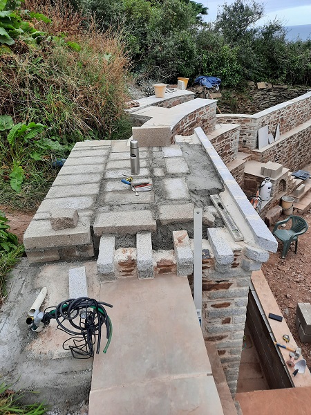
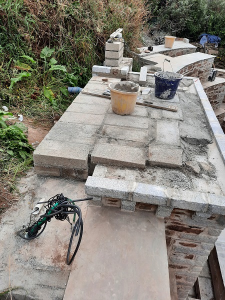
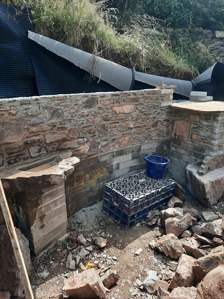
At the same time we finished off the top of the water feature by bringing it up level using concrete block to form the viewing area.
It was butterfly season and there was an abundance of these insects around. This particular species is called a ‘Woodland Brown’.

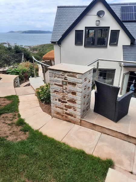
Next we built two walls at ground level either side of the water feature, the one on the right of the water feature curved around to the steps and topped off with an Indian sandstone coping.
The wall on the left swept around to the B.B.Q. These walls were built level about two feet (600mm) above the finished ground level but left lower than the walls of the water feature. These walls formed raised planters and when filled with topsoil it would cover up the concrete blockwork that had been built earlier at the base of the retaining wall.
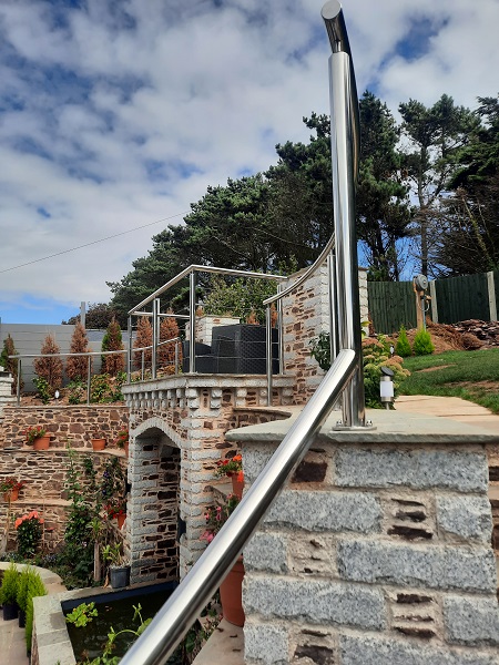
Now that the viewing platform was more or less levelled off we built a couple of piers on the two back corners. A stainless steel handrail would be fixed later to the piers which would go around the edge of the viewing platform. We didn’t want anyone falling off at this height. The drop down below was more than three and half metres.
Cables for lighting were built into the backs of the piers.
One of the piers had a cupboard built into the back of it which would house some of the electrics for the water pump and lighting.
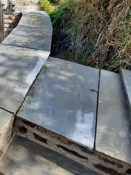
With the piers completed we could now pave the top of the viewing platform with the Indian sandstone.
After the viewing platform and piers were completed, a machine was brought in and the upper ground levels were graded to suit.
Lights were incorporated into the back of the piers as you lead onto the viewing platform.
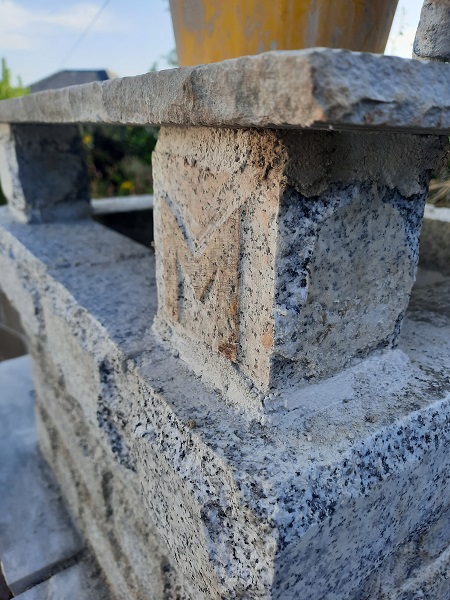
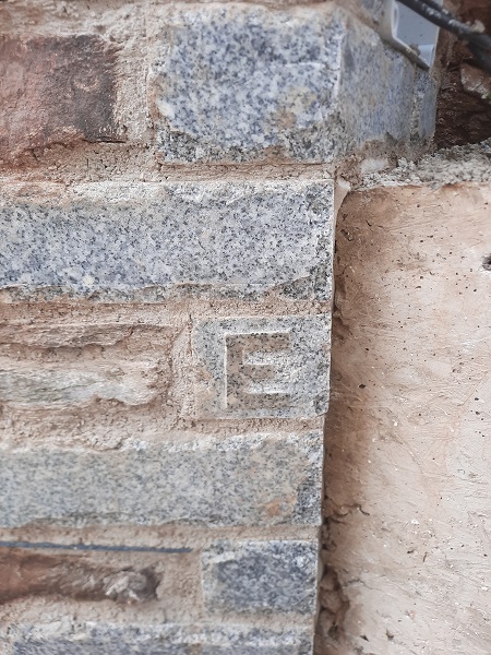
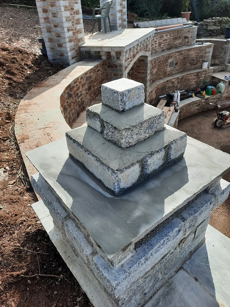
MERLIN’S SIGNATURE
After a couple of weeks into the project we decided to incorporate yet another feature into the wall. This consisted of carving the letters ‘MERLIN ‘ into six small cubes of granite. Each cube being approximately three and a half inches (90mm) square. These were then discretely built into the new stonework as we went along
The letter ‘M’ was built into the top right hand corner of the chimney.
The letter ‘E’ was set into the quoin were the new wall joined into the concrete retaining wall down the side of the new house.
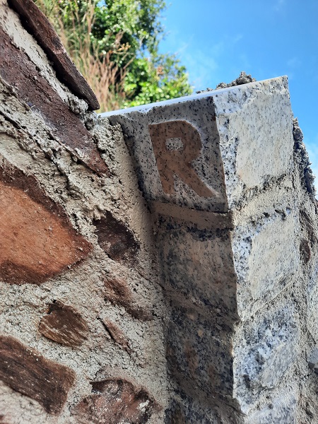
The letter ‘R’ was used for the underside of one of the arch stones that formed the recessed niche in the side of the steps.
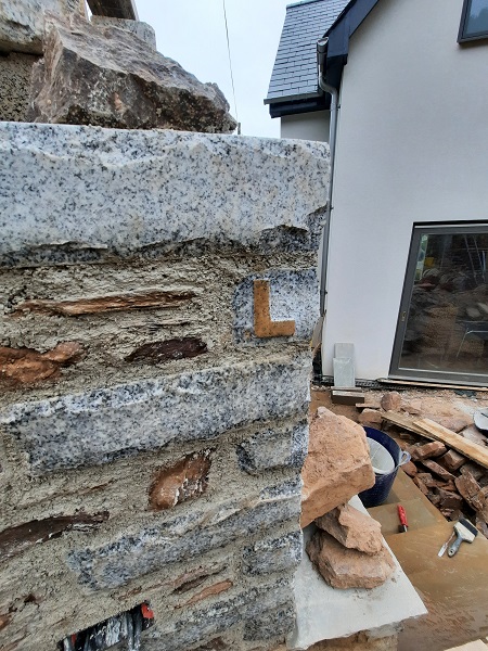
The letter ‘L’ is built into the right hand quoin going up new steps.
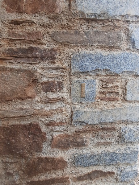
The letter ‘I’ was set into the internal right hand reveal of the water feature.
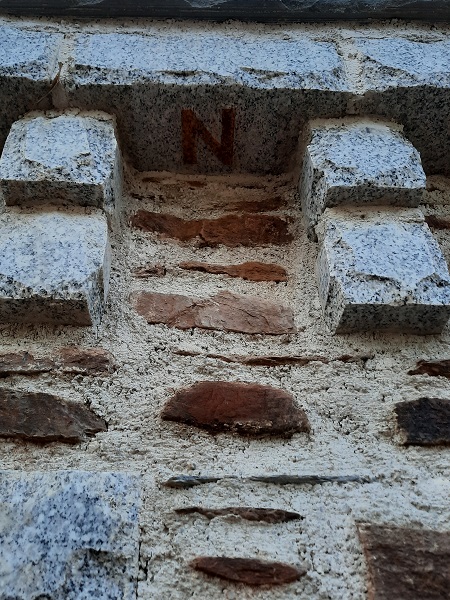
And finally, the letter ‘N’ is positioned under the left hand side of the corbelled machicolations above the water feature.
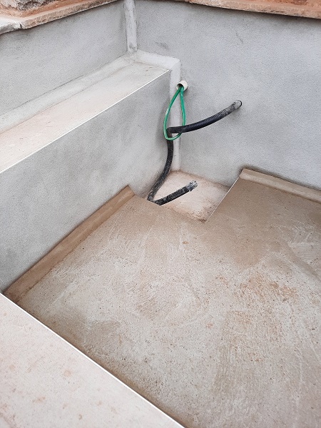
By now this large retaining wall was more or less complete, but we did have a few little things to tidy up. One of them being the water feature which we had to tank to ensure it didn’t leak. We started by applying a scratch coat of waterproof sand and cement render to the walls.
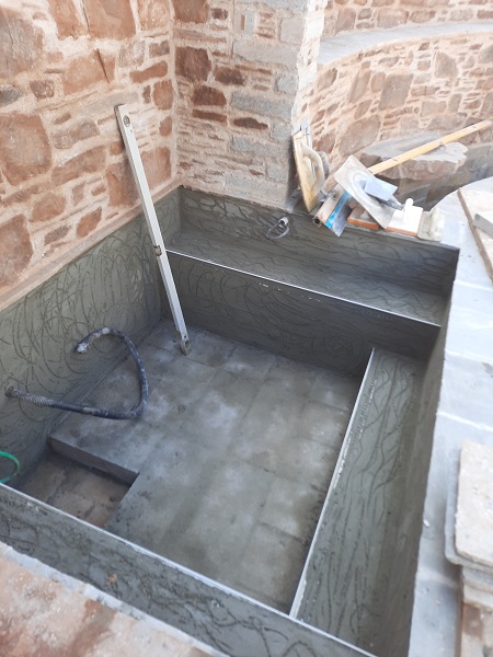
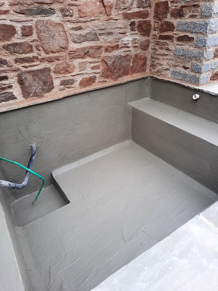
Ledges had been incorporated within the water feature to accommodate different aquatic plants. A sump was also created within the floor which would make it easier in the future to empty out the water for maintenance. A second coat of water proof render was applied and a two inch (50mm) sand and cement fillet was formed to all corner joints. This strengthens these areas as it can be vulnerable to cracking due to water pressure once the water feature if filled up. The reservoir for the water feature when filled would hold approximately the weight of two tons of water.
Once the render had set, two good coats of tanking slurry was applied to the walls to make sure it was one hundred percent water proof.
And just to be absolutely sure, once this was cured this would eventually be covered with two coats of resin based pond paint. Another little job that needed finishing was the top of the chimney, although just a small job it really was the icing on the cake!
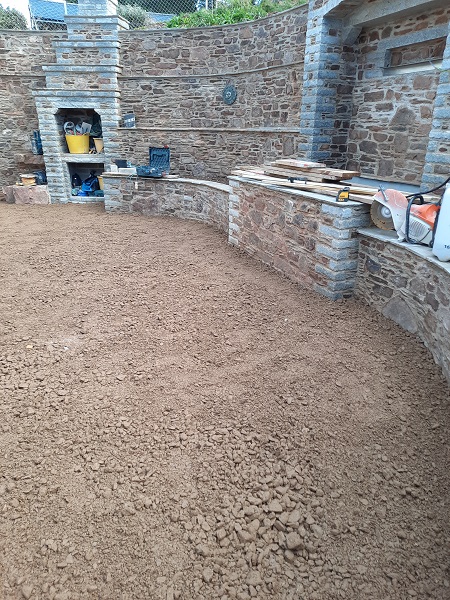
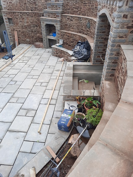
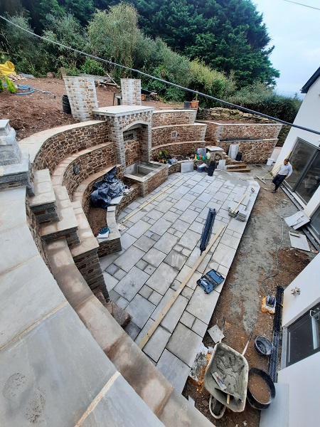
With the water feature buttoned up and the top of the chimney finished, the site was cleared up and hardcore was brought in and compacted down in preparation for the new paving.
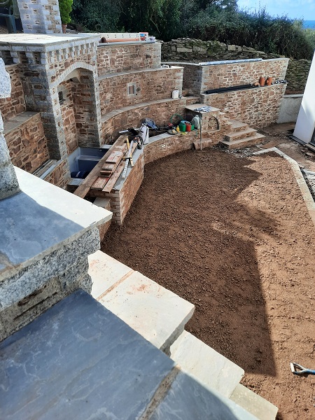
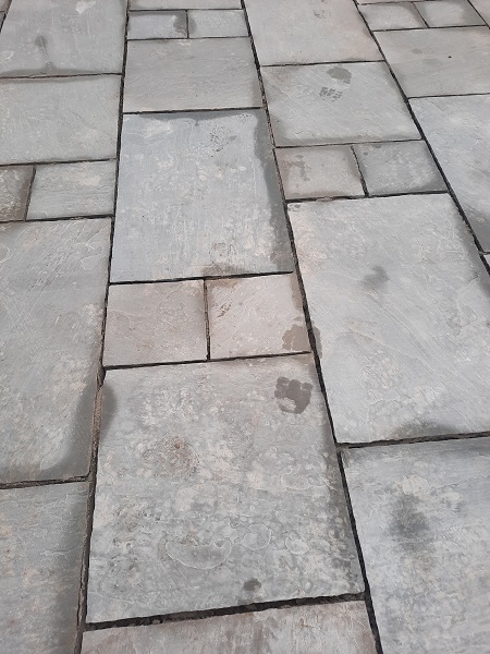
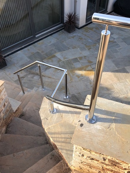
Indian sandstone was laid down in the classic Roman style. This pattern, used extensively by the Romans, is laid down in rows consisting of random lengths and you’ll find many pavements and roads all over the world using this classic style.

Once the paving was finished it was time to get the stainless steel handrails put in place around the top of the retaining wall,
along with the viewing platform,
and of course the staircase.
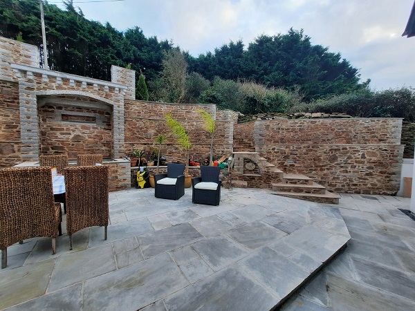
Finally it was time to switch those lights on…..
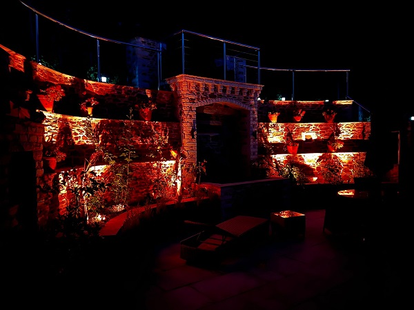
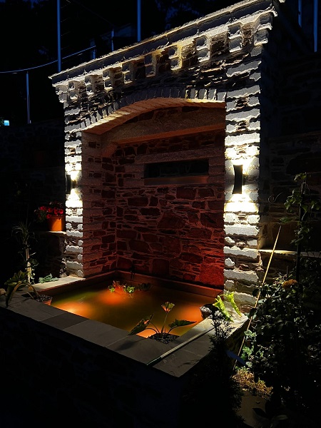
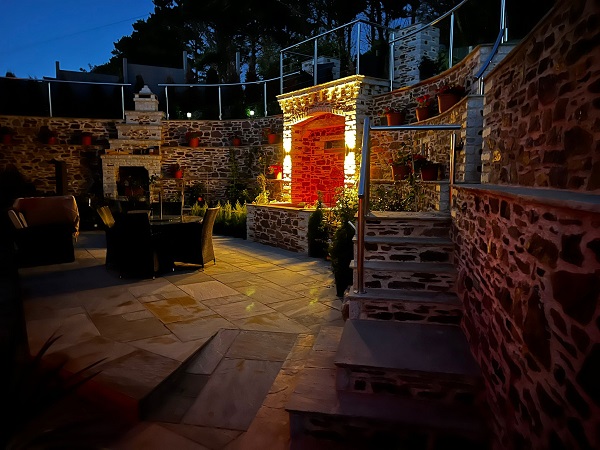
…..and party!